How do you know if your CR6 is maxed out?
by Eric Schmidt | Updated: 02/18/2025 | Comments: 1
Blog Topics
Area / Application


Product Category


Corporate / News
Search the Blog
Subscribe to the Blog
Get an email when a new article is posted. Choose the topics that interest you most.
Suggest an Article
Is there a topic you would like to learn more about? Let us know.
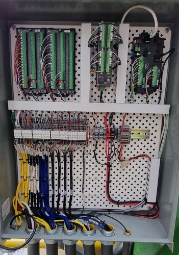
Just how many AM16/32B multiplexers can you really add to your CR6 Automated Monitoring Platform? At what point do you hit the limit? What is truly safe?
As an Application Specialist in Campbell Scientific’s Infrastructure Group, I get a lot of customer questions about squeezing the most out of a CR6 and other data loggers—specifically, how to connect as many sensors as possible. If you’ve ever found yourself staring at a bundle of wires, wondering, “Can I fit just one more multiplexer?” then this blog article is for you.
In this article, I’ll explain the safest and most effective ways to add AM16/32B multiplexers to a CR6 without overcomplicating your setup.
A Few Ground Rules Before We Begin
Before we start stacking multiplexers like a high-stakes game of Tetris, here are a few important things to keep in mind:
- The following solutions are SAFE. Yes, you can push the limits even further, but that requires advanced expertise, custom programming, and extra support. The configurations listed in this article strike the right balance between maximizing channels and keeping things manageable.
- Clock lines will be shared. This is okay as long as each Reset line has a unique channel. That said, fitting more than three wires into a single port gets tricky, so we’ll stick to three wires maximum per port.
- You’ll need to use our CRBasic programming language to write some code. (The Short Cut Program Generator for Windows won’t cut it for these setups.)
Keeping these ground rules in mind, let’s look at some different configuration options using a variety of sensor types.
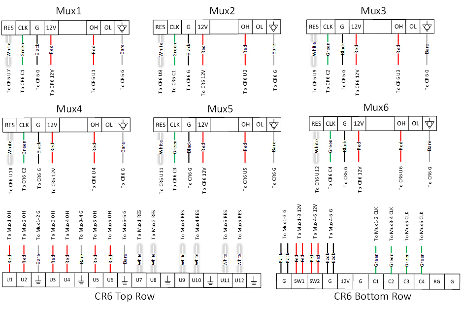
Vibrating Wire Sensors with Three AM16/32Bs in 4 by 16 Mode
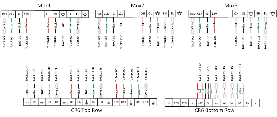
Click the diagram for a larger image.
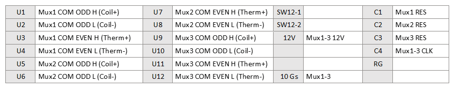
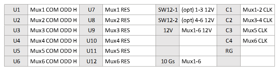
Click the table for a larger image.
Vibrating wire sensors have four wires plus a shield wire that goes to ground. To connect them, each AM16/32B multiplexer will require:
- Four Universal (U) channels for measurements
- One control port for the Reset line
- One shared control port for the Clock line
With this setup, a single CR6 can handle 48 vibrating wire sensors with thermistors (3 multiplexers × 16 sets of 4 channels).
This configuration strikes a great balance between maximizing sensor capacity and keeping the wiring manageable. If you're working with a large-scale system, this setup helps keep everything streamlined while ensuring reliable measurements.
Differential Voltage Sensors with Four AM16/32Bs in 2 by 32 Mode

Click the diagram for a larger image.
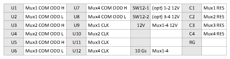
Click the table for a larger image.
Differential voltage sensors keep things simple with just two wires. To connect them, each AM16/32B multiplexer will need:
- Two U channels for measurements
- One control port for the Reset line
- One shared control port for the Clock line
With this setup, a single CR6 can handle 128 differential voltage sensors (4 multiplexers × 32 pairs of channels).
A quick note: This configuration breaks my rule by fitting four wires into a single port. To keep things clean, you might want to shift some of the 12V lines to Switch 12V ports and turn them on in the code. In the table above, I’ve marked these as optional (opt).
This setup gives you a lot of measurement capacity while keeping wiring manageable; just be mindful of the power distribution.
Single-Ended Voltage Sensors with Six AM16/32Bs in 2 by 32 Mode
Click the diagram for a larger image.
Click the table for a larger image.
Single-ended voltage sensors keep it simple: one wire for measurement and one for ground. To connect them, each AM16/32B multiplexer will need:
- One U channel for measurement
- One control port for the Reset line
- One shared or single control port for the Clock line
With this setup, a single CR6 can handle 192 single-ended voltage sensors (6 multiplexers × 32 channels each).
One thing to watch out for: As with differential voltage sensors, this setup can push the limit of how many wires you can fit into a single port. To avoid a messy or unreliable connection, consider shifting some of the 12V lines to Switch 12V ports and turning them on in the code.
This configuration maximizes sensor capacity while keeping power and wiring challenges in check.
Bridge Measurements with Three AM16/32Bs in 4 by 16 Mode
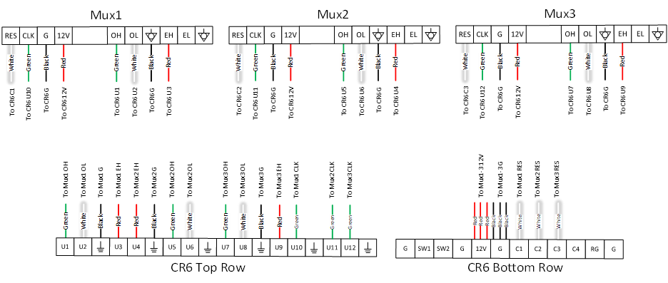
Click the diagram for a larger image.
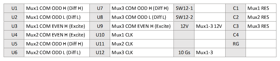
Click the table for a larger image.
Bridge measurements, such as those from bonded-foil strain gauges or load cells, require a bit more wiring. Each sensor has:
- Two wires for the differential measurement
- One wire for excitation
- One wire for ground
To connect them, each AM16/32B multiplexer will need:
- Three U channels for measurement
- One control port for the Reset line
- One control port for the Clock line
- One ground channel
With this setup, a single CR6 can handle 48 bridge measurement sensors (3 multiplexers × 16 sets of 4 channels). Please note that this is for full Wheatstone Bridge measurements. If you are using quarter-bridge or half-bridge measurements, you will need the appropriate completion resistor modules on each channel.
This configuration provides a reliable way to scale up bridge-based sensors while keeping channel assignments straightforward.
Conclusion
The configurations I’ve shown here represent the safe maximum number of AM16/32B multiplexers that you can attach to a CR6 while measuring various types of sensors. Pushing beyond these limits introduces extra complexity—more coding, maintenance headaches, and the potential for errors—all of which can quickly offset any cost savings you might be aiming for.
That said, the ability to add so many sensors on one data logger is a game-changer. It simplifies your system, cuts down on hardware costs, and helps streamline large-scale data acquisition (DAQ) setups.
I hope this article clears up some of the mystery about how much you can fit on a single CR6, especially for those of you who regularly design and install large DAQ systems. With these configuration solutions, you'll be able to maximize your sensor counts without compromising your data reliability.
Do you have questions about how to maximize your CR6? Please each out to our support and implementation team or sales team, as we are happy to help answer any questions you have!


About the Author
 Eric Schmidt is an Application Specialist in the Infrastructure Group at Campbell Scientific, Inc. He works with customers on the technical aspect of building measurement systems; helps provide trainings for all of Campbell Scientific’s international offices; and attends conferences related to dams, mines, and geotechnology. He received his bachelor’s degree in biological engineering from Utah State University. In his spare time, he enjoys canyoneering and composing music.
Comments
ariklee | 02/19/2025 at 05:45 PM
Fantastic! Thanks Eric
Please log in or register to comment.