More accurate in soils with high bulk EC


Overview
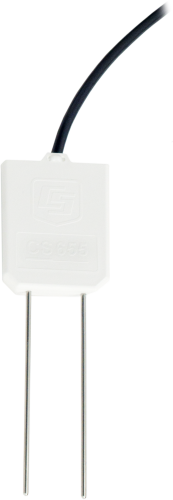
The CS655 is a multiparameter smart sensor that uses innovative techniques to monitor soil volumetric-water content, bulk electrical conductivity, and temperature. It outputs an SDI-12 signal that many of our dataloggers can measure. It has shorter rods than the CS650, for use in problem soils.
Read More
Benefits and Features
- Larger sample volume reduces error
- Measurement corrected for effects of soil texture and electrical conductivity
- Estimates soil-water content for a wide range of mineral soils
- Versatile sensor—measures dielectric permittivity, bulk electrical conductivity (EC), and soil temperature
Images
Detailed Description
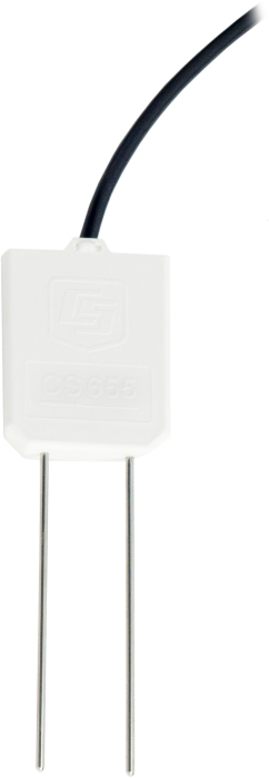
The CS655 consists of two 12-cm-long stainless steel rods connected to a printed circuit board. The circuit board is encapsulated in epoxy and a shielded cable is attached to the circuit board for data logger connection.
The CS655 measures propagation time, signal attenuation, and temperature. Dielectric permittivity, volumetric water content, and bulk electrical conductivity are then derived from these raw values.
Measured signal attenuation is used to correct for the loss effect on reflection detection and thus propagation time measurement. This loss-effect correction allows accurate water content measurements in soils with bulk EC ≤8 dS m-1 without performing a soil-specific calibration.
Soil bulk electrical conductivity is also calculated from the attenuation measurement. A thermistor in thermal contact with a probe rod near the epoxy surface measures temperature. Horizontal installation of the sensor provides accurate soil temperature measurement at the same depth as the water content. Temperature measurement in other orientations will be that of the region near the rod entrance into the epoxy body.
Compatibility
Please note: The following shows notable compatibility information. It is not a comprehensive list of all compatible products.
Dataloggers
| Product | Compatible | Note |
|---|---|---|
| CR1000 (retired) | ||
| CR1000X (retired) | ||
| CR300 (retired) | ||
| CR3000 (retired) | ||
| CR310 | ||
| CR350 | ||
| CR6 | ||
| CR800 (retired) | ||
| CR800 (retired) | ||
| CR850 (retired) | ||
| CR850 (retired) |
Additional Compatibility Information
RF Considerations
External RF Sources
External RF sources can affect the probe’s operation. Therefore, the probe should be located away from significant sources of RF such as ac power lines and motors.
Interprobe Interference
Multiple CS655 probes can be installed within 4 inches of each other when using the standard data logger SDI-12 “M” command. The SDI-12 “M” command allows only one probe to be enabled at a time.
Optional Installation Tool
CS650G Rod Insertion Guide Tool
The CS650G makes inserting soil-water sensors easier in dense or rocky soils. This tool can be hammered into the soil with force that might damage the sensor if the CS650G was not used. It makes pilot holes into which the rods of the sensors can then be inserted.
Specifications
| Measurements Made | Soil electrical conductivity (EC), relative dielectric permittivity, volumetric water content (VWC), soil temperature |
| Required Equipment | Measurement system |
| Soil Suitability | Short rods are easy to install in hard soil. Suitable for soils with higher electrical conductivity. |
| Rods | Not replaceable |
| Sensors | Not interchangeable |
| Sensing Volume | 3600 cm3 (~7.5 cm radius around each probe rod and 4.5 cm beyond the end of the rods) |
| Electromagnetic | CE compliant (Meets EN61326 requirements for protection against electrostatic discharge and surge.) |
| Operating Temperature Range | -50° to +70°C |
| Sensor Output | SDI-12; serial RS-232 |
| Warm-up Time | 3 s |
| Measurement Time | 3 ms to measure; 600 ms to complete SDI-12 command |
| Power Supply Requirements | 6 to 18 Vdc (Must be able to supply 45 mA @ 12 Vdc.) |
| Maximum Cable Length | 610 m (2000 ft) combined length for up to 25 sensors connected to the same data logger control port |
| Rod Spacing | 32 mm (1.3 in.) |
| Ingress Protection Rating | IP68 |
| Rod Diameter | 3.2 mm (0.13 in.) |
| Rod Length | 120 mm (4.7 in.) |
| Probe Head Dimensions | 85 x 63 x 18 mm (3.3 x 2.5 x 0.7 in.) |
| Cable Weight | 35 g per m (0.38 oz per ft) |
| Probe Weight | 240 g (8.5 oz) without cable |
Current Drain |
|
| Active (3 ms) |
|
| Quiescent | 135 µA typical (@ 12 Vdc) |
Electrical Conductivity |
|
| Range for Solution EC | 0 to 8 dS/m |
| Range for Bulk EC | 0 to 8 dS/m |
| Accuracy | ±(5% of reading + 0.05 dS/m) |
| Precision | 0.5% of BEC |
Relative Dielectric Permittivity |
|
| Range | 1 to 81 |
| Accuracy |
|
| Precision | < 0.02 |
Volumetric Water Content |
|
| Range | 0 to 100% (with M4 command) |
| Water Content Accuracy |
|
| Precision | < 0.05% |
Soil Temperature |
|
| Range | -50° to +70°C |
| Resolution | 0.001°C |
| Accuracy |
|
| Precision | ±0.02°C |


Downloads
CS650 / CS655 Firmware v.2 (429 KB) 02-12-2015
Current CS650 and CS655 firmware.
Note: The Device Configuration Utility and A200 Sensor-to-PC Interface are required to upload the included firmware to the sensor.
Frequently Asked Questions
Number of FAQs related to CS655: 51
Expand AllCollapse All
-
Damage to the CS650 or the CS655 electronics or rods cannot be repaired because these components are potted in epoxy. Cable damage, on the other hand, may possibly be repaired. For more information, refer to the Repair and Calibration page.
-
The bulk electrical conductivity (EC) measurement is made along the sensor rods, and it is an average reading of EC over that distance at whatever depth the rods are placed.
-
Mine tailings are highly corrosive and have high electrical conductivity. Some customers have successfully used water content reflectometers, such as the CS650 or the CS655, to measure water content in mine tailings by coating the sensor rods with heat-shrink tubing. This affects the sensor output, and a soil-specific calibration must be performed. Care must be taken during installation to avoid damaging the heat-shrink tubing and exposing the sensor’s rods. In addition, covering the sensor’s rods invalidates the bulk electrical conductivity reading. Unless the temperature reading provided by the CS650 or the CS655 is necessary, a better option may be to use a CS616 with coated rods.
-
Period average and electrical conductivity readings were taken with several sensors in solutions of varying permittivity and varying electrical conductivity at constant temperature. Coefficients were determined for a best fit of the data. The equation is of the form
Ka(σ,τ) = C0*σ3*τ2 + C1*σ2*τ2 + C2*σ*τ2 + C3*τ2 + C4*σ3*τ + C5*σ2*τ + C6*σ*τ + C7*τ + C8*σ3 + C9*σ2 + C10*σ + C11
where Ka is apparent dielectric permittivity, σ is bulk electrical conductivity (dS/m), τ is period average (μS), and C1 to C11 are constants.
-
If information is available on soil texture, organic matter content, and electrical conductivity (EC) from soil surveys or lab testing of the soil, it should be possible to tell if the soil conditions fall outside the range of operation of the sensor. Without this information, an educated guess can be made based on soil texture, climate, and management:
- Soil that is coarse textured (such as sand, loamy sand, or sandy loam) works well with a CS650 if the EC is low.
- If the soil is located in an arid or semiarid region, it may have high EC.
- If the soil is frequently fertilized or irrigated with water that has higher EC, it may have high EC.
- If the climate provides enough rain to flush accumulated salts below the root zone, the EC is expected to be low and suitable for a CS650.
When in doubt about soil texture and electrical conductivity, Campbell Scientific recommends using a CS655 because of the sensor’s wider range of operation in electrically conductive soils, as compared with the CS650.
-
The CWS655 is a wireless sensor with measurement electronics, radio, and power supply all integrated in a single device. The CWS655, however, requires the use of a CWB100 base station radio connected to a data logger. Only the rods of the CWS655 should be buried in the soil; burying the body of the CWS655 will prevent the sensor from communicating with the CWB100.
The CS655 is a cabled multiparameter smart sensor that sends data by RS-232 serial or SDI-12 communication through a direct connection to a data logger. The CS655 is suitable for burial at any depth.
-
A CS650 or CS655 can be ordered with an SDI-12 address option of -VS. With the -VS option, the SDI-12 address is set at the factory before the sensor is shipped. The last digit of the sensor’s serial number becomes that sensor’s SDI-12 address. Typically, the -VS option is chosen when there are multiple sensors that will communicate with the data logger on the same SDI-12 communications terminal.
If the -VS option is not selected when ordering, the CS650 or CS655 will ship with its SDI-12 address set to 0 (the default -DS option). The address can be changed to a non-zero value using the A200 Sensor to PC Interface or by connecting the sensor to an SDI-12 communications terminal and sending the aAb! Command as described in the “SDI-12 Sensor Support” appendix of the CS650/CS655 manual.
-
Modifications to the CS650 or CS655, including shortening the cable, will void the warranty. However, shortening the cable will not affect the sensor’s performance. If a decision is made to shorten the cable, care should be taken to avoid damaging the cable jacket and exposing bare wire except at the ends that connect to the data logger or multiplexer terminals.
-
Campbell Scientific does not recommend using the CS650 or the CS655 to measure water content in compost. A compost pile is a very hostile environment for making dielectric measurements with soil water content sensors. All of the following combine to make it very difficult to determine a calibration function: high temperature, high and varying electrical conductivity, high organic matter content, heterogeneity of the material in the pile, changing particle size, and changing bulk density. The temperature and electrical conductivity values reported by the CS650 or CS655 may give some useful information about processes occurring in the compost pile, but these sensors will not be able to give useful readings for water content.
-
Yes. Keeping the sensor rods parallel during installation is especially difficult in gravel, but it can be done. Gravel has large pore spaces that drain quickly, so the water content readings will likely show rapid changes between saturation and very dry. If small changes of water content at the dry end are of interest, a soil-specific calibration may need to be performed to convert period average directly to volumetric water content.
Case Studies

At the northern edge of Jamaica, fresh water from a limestone aquifer and the Martha......read more
The Utah Geological Survey, supported by the Utah Division of Water Rights, has constructed a......read more
International partnerships for sustainable innovations Improved water use in agriculture is essential to successfully adapt to......read more

This case study discusses the integration of CPEC310 and AP200 systems to explore the theories......read more
Privacy Policy Update
We've updated our privacy policy. Learn More